Saturday 31 May 2014

WEEK 13 & WEEK 14

Date: 7/5/14

Introduction

This week is the last week before project presentation day will be held. All the requirements that needed for that week should be prepared properly. Student shall present their complete project outcome as scheduled by Campus which is at the end of week 14. Failure to attend the presentation will cause student to receive the failure grade (F). The project presentation will be held at Gemilang Hall and start from 8.00 am till 12.30 pm. Students will be assessed by two persons of invited assessor from related department with the project title.

Objective
  • To finalize a preparation that should will be made for presentation day
  • To ensure all the assessment criteria is achieved perfectly
  • To makes some preparation for Q&A session
Problem Encountered

All the requirement that needed such as project poster, project prototype and others has been made and meets all the required assessment criteria which means the first and second of the objective is achieved perfectly. However, a bit of problem occurs in makes some preparation for Q&A session. It is in terms of student did not know what questions that would be asked by supervisors in that session. As a solution, the proposal presentation assessment that prepared by FYP committee will be made as a guideline in preparation for Q&A session.

Project Description

The entire criteria that needed in the project presentation day will be fulfilled by referring the proposal presentation assessment that given by FYP committee. Below is a copy of the documents that given:-

Figure 1: Project Presentation Assessment

Figure 2: Project Presentation Assessment (Cont.)

Figure 3: Project Presentation Assessment (Cont.)

All the preparation for the project presentation day will be referred from this documents.

Project Outcome

Referring from the official website of UniKLBMI-FYP, under list of deg sem 2 assessors, it shows that for this project it will be assessed by (1) Sir. Mohamed Razif Mohd Noordin and (2) Mdm. Zurin Zuraida Bte Abu Baharin. As a conclusions, everything has been prepared and achieve all required assessment criteria. Hopefully, everything is smoothly during that presentation day.

WEEK 12

Date: 28/4/14

Introduction

Project presentation is one of the assessment in FYP 2 that will be made at the end of semester 7. The assessment is based on individually basis. It will be assessed by Project Supervisor and Invited Assessor. The overall mark obtained by students is the average mark given by Supervisor and second Assessor. This week, a preparation for project presentation day will be made and discussed clearly.

Objective
  • To make some preparations before project presentation day
  • To making a project poster according to the assessment criteria that given
Problem Encountered

From the activity on this week, its does not have much problem because the contents that should be put into a poster is from the assignments that has been made along this semester. The things that need to be made only extract all gathered information briefly, concise and easy to understand.

Project Description

All gathered information will be extracted in a simple way to understand according to the assessment criteria that needed. The poster also will be decorated to look more attractive because sometimes people will bored when too much of word inserted in the poster. As a solution, several information will be described by using a SmartArt graphic to visually communicate information. A background picture also will be used and inserted in the poster.

Project Outcome

Below is the poster that have been made for project presentation day.

Figure 1: Project Poster

The completed poster will be shown to the project supervisors before project presentation day. As a conclusions, all tasks for this week completed perfectly and the poster that has been made has been approved by project supervisor. For the next progress report, the things that made before/during/after presentation day will be briefly discussed.

Friday 30 May 2014

WEEK 11

Date: 22/4/14

Introduction

Project costing is the amount of the overall cost to build a project that usually contains the amount of cost for each parts of hardware, software and miscellaneous part used in the project. This week, the costing for that part will be discussed and shown in details.

Objective 
  • To list and show cost for each part of hardware, software and miscellaneous part used in the project.
  • To shows the total cost of project.
Problem Encountered

In this activity, the problem that encountered is in terms of to find a good components at low prices. It is because usually the good components will be sold at high prices. Several initiative will be taken to solve this problem such as make a observation at a few store that sell required components at low prices before buying that component.

Project Description

When the store that sell required components at needed prices have been found, buying process will be made till all the required components is obtained. Then, each part of components that have been purchased together with the prices is recorded in three part such mentioned in the objective above. The results from this activities are as shown in the Project Outcome below.

Project Outcome 

There are three parts in this project outcome which are hardware costing, software costing and miscellaneous costing. Below is the figure that shows each parts of this costing together with the total cost of project.

Hardware Costing

Figure 1: Hardware Costing
   
Software Costing

Figure 2: Software Costing

Miscellaneous Costing

Figure 3: Miscellaneous Costing

Total Cost

Figure 4: Total Costing

Total cost of this project is about RM 1229.35. It is quite expensive. However, this is the best choice from various electronics store that have. In the next progress report, all works related with the project presentation will be discussed and shown clearly.

Tuesday 20 May 2014

WEEK 10

Date: 14/4/14

Introduction

In this parts of progress report, the things that will be discussed is about the functional tests for the overall project. It covers the functional tests for both part which are pole and consumer based system together with the bluetooth module. All the transmitted data from pole based system and the received data at the consumer based system also will be shown through the LCD display. Further, the bluetooth module that used in this project also will paired and connected to the handphone or other devices that can paired with the bluetooth module used to demonstrates the actual result needed in the entire project.

Objective
  • To makes a functional tests to the overall part of project.
  • To ensure all required criteria and the expected results in this project meets.
Problem Encountered

This project do not have any problem because the test procedure that made is only to obtain the expected results from the overall project. Simply, it only need to 'plug and play' and record all the results that obtained.

Project Description

Step 1

First of all, power up main circuit by connects the plug top to the socket outlets. Once connected, switch on both MCB and both digital energy meter will display current power usage and measured in kWh. Below is the result from this part.

Figure 1: Power usage from both part of measurement

Step 2

Switch on both Arduino board and the LCD will display the characters that have been programmed. Once completed displays all the characters, each LCD at pole and consumer based system will display current reading depend on the loads that used. The results for this part is as that have been shown on previous week (week 8 and week 9) under project outcome.

Step 3

Download Bluetooth Terminal software from Google Play website and install this software to the handphone to display all the data that transmitted from the bluetooth module. The results for this part as shown in the Project Outcome below and demonstrated in two different condition which are without unauthorized loads and with unauthorized loads.

Project Outcome 

The results obtained from the overall part of this activities are as follows:-

Without unauthorized loads

Figure 2: Result for without unauthorized loads
    
With unauthorized loads

Figure 3: Result for with unauthorized loads

Based on the results obtained from the overall part of this activities, it shows the expected results is achieved according to the project requirement. Thus, for the next progress report, all things that related with the project costing will be shown and discussed in details.

Monday 19 May 2014

WEEK 9

Date: 7/4/14

Introduction

This progress report will discuss about the software development that made for consumer based system. The things that will be discussed is in terms of the source code for consumer based system together with the project outcome from this activity. However, it still relate with the works that made in the previous week (week 8) because a few parts of source code and data are from the pole based systems.

Objective
  • To writing and maintaining the source code.
  • To modify and reuse the source code with respect to the desired outcome of the project.
  • To test and integrate the source code with the components used in the project.
Problem Encountered

The problem encountered from this activity is in terms of to find the source code for receive the transmitted data from pole based system. It is because the source code that used for the receiving part is different with the transmitting part. It is because the source code that used for the receiving part is different with the transmitting part. On the other hand, the compatibility of the source code with the RF module also need to be considered because it will be affect to the speed of data that transmitted to the receiver. Thus, as a solution, various websites about the source code for RF module together with the method of 'trial and error' will be used to solve this problems until success.

Project Description 

Below is the steps used in this part of software development:-

Step 1

Open a Arduino IDE and check the libraries that have in the IDE that used for confirmation. In this part the libraries that used is similar with the previous part. Thus, no additional libraries will be installed. 

Step 2
Sketch the source code according to the required codes in the Arduino IDE and the source code that have been made is such as below.

Figure 1: Source code for consumer based system
     
Figure 2: Source code for consumer based system (Cont.)

Figure 3: Source code for consumer based system (Cont.)

Step 3

Once all required source code is completed sketched in the text editor, all the completed source code need to verified before uploaded in the Arduino board. Below is the result obtained from the verification of source code that made in the Arduino IDE.

Figure 4: Source code verification results

Step 4

When the source code is verified not have an errors, set the Arduino board model and COM that currently used in the Arduino IDE. In this project, the Arduino board model and current USB port (COM) that used is Arduino Mega 2560 and connected to the COM 11. Once selected, both of this information will appears at the bottom of Arduino IDE such as shown in the Figure 5 below.

Figure 5: Current Arduino board model and USB port

Step 5

Upload all the source code in the Arduino by using the button for compile and upload sketch to Arduino at the top of Arduino IDE. Once completed uploaded, it can be seen directly on the hardware part (LCD) and the results as in the Project Outcome below.

Project Outcome

Below is the results obtained from the source code that made for consumer based system and demonstrated in three different condition together with the current reading that received from pole based system.

Figure 6: LCD displays current reading for three different conditions together
with the current reading that received from pole based system

Based on the Figure 6 above, it shows all the required results have been achieved according to the criteria that needed for the consumer based system. Thus, the functional tests for the overall project together with the Bluetooth module will be made and discussed in the next progress report.

WEEK 8

Date: 31/3/14

Introduction

Software development is the development of a software product. The term "software development" is used to refer to the activity of computer programming, which is the process of writing and maintaining the source code. This week, the development of software will be made, discussed and shown according to the specific requirement needed in the entire project.

Objective
  • To writing and maintaining the source code.
  • To modify and reuse the source code with respect to the desired outcome of the project.
  • To test and integrate the source code with the components used in the project.
Problem Encountered

Software development is usually implemented by using a specific software and based on the microcontroller board or integrated circuit (IC) that used. As mentioned before, this project (ETDMS) is controlled by using Arduino Mega 2560 and this microcontroller board have their own software application known as Arduino IDE. This software application provides comprehensive facilities to computer programmers for software development. However, it have a few things that need to known and learned in terms of the language and libraries because both of this part is very important in the software development. Even it have been provided in the Arduino website, it will become a problem if the language and libraries that used is not compatible and suitable with the components. Thus, as a solution, each required libraries will be ensured compatible, suitable and installed with the IDE together with the correct language/source code.

Project Description

The Arduino IDE contains a text editor for writing code, a message area, a text console, a toolbar with buttons for common functions, and a series of menus. It connects to the Arduino hardware to upload programs and communicate with them. The following is the procedures for the overall parts of this activities.

Step 1

First of all, the Arduino IDE need to identified and the Figure 1 below shows the Arduino IDE together with the explanation for each parts of the Arduino IDE.

Figure 1: The Arduino IDE
        
Step 2

Once all term in the IDE window is identified, check the libraries as shown in the Figure 2 below.

Figure 2: List of libraries installed in the Arduino IDE.

Step 3

When all the required libraries have been installed in the Arduino IDE, sketch the source code in the text editor according to the project requirement. Since this project (ETDMS) uses two microcontroller board, the source code also should be made in two parts named as (1) pole based systems and (2) consumer based systems.

Figure 3: Source code for pole based system

Figure 4: Source code for pole based system (Cont.)

Step 4

Once all required source code is completed sketched in the text editor, all the completed source code need to verified before uploaded in the microcontroller board. Below is the result obtained from the verification of source code that made in the Arduino IDE.

Figure 5: Source code verification results
 
Step 5

When the source code is verified not have an errors, set the Arduino board model and COM that currently used in the Arduino IDE. In this project, the Arduino board model and current USB port (COM) that used is Arduino Mega 2560 and connected to the COM 11. Once selected, both of this information will appears at the bottom of Arduino IDE such as shown in the Figure 6 below.

Figure 6: Current Arduino board model and USB port
   
Step 6

Upload all the source code in the Arduino by using the button for compile and upload sketch to Arduino at the top of Arduino IDE. Once completed uploaded, it can be seen directly on the hardware part (LCD) and the results as in the Project Outcome below.

Project Outcome

Below is the results obtained from the source code that made for pole based system:-

Figure 7: LCD displays current reading for three different conditions
     
The Figure 7 above shows the results that obtained from the source code that made for pole based system. All needed data that should be displayed on the LCD for pole based system have been achieved according to the required criteria. Further, this data need to transmitted to the consumer based system using RF module and suitable source code to allows the data obtained from pole based system can be transmitted and received at the consumer based system repeatedly and according to the loads that used over time. Thus, the other source code for that purpose will be sketched and shown in the next progress report.

Monday 28 April 2014

WEEK 7

Date: 17/3/14

Introduction

Hardware development is a parts of where all the components that has been tested will be installed according to the wiring diagram that designed in the previous week. This week, all works that relate with this matter will be discussed and shown clearly.

Objective
  • To install all the components related with the project.
  • To wire the components according to the wiring diagram that designed.
Problem Encountered

All works that made is based on the project design and wiring diagram that has been implemented before. Thus, it does not give any problem either before, during or after do this activities. However, all the wire connection and components is ensured installed on the right connection and arranged properly.

Project Description

The installation and wiring for this project is made separately. The following is the procedures to install and wire all the components that used in this project.

Step 1
  
Each part of component is installed one by one and arranged properly according to the project design but before that a surface of plywood need to painted to look nice and tidy. In this project, the plywood is used as base where all the components will be mounted on this plywood. The Figure 1 below shows the plywood that have been painted with black colour.

Figure 1: A surface of plywood that have been painted.

Step 2

When the paint is completely dry, all the components will mounted on the painted plywood and arranged according to the project design. Below is the figure that shows the components that have been arranged and mounted on the plywood.

Figure 2: A few components that have been completed mounted
on the painted plywood.
 
Step 3

After all the components completed mounted on the plywood, each part of component will be wired according to the wiring diagram and the result is such as Figure 3 below.

Figure 3: Each part of electrical and electronic is wired separately.

Step 4

Once all parts of electrical appliances is wired completely, a wiring job for the electronic part will be made. This part is made side by side to avoid any mistake in the wiring. Below is the figure that shows both parts of project that have been wired completely.

Figure 4: This parts are referred as pole based systems
and have been wired completely.
  
Figure 5: This parts are referred as consumer based systems
and have been wired completely.

All parts of the hardware have been installed and wired based on the project design and wiring diagram that have been designed before. Thus, the results that obtained from this activities is such as the figure that shown in the Project Outcome below.

Project Outcome

Figure 6: The end result for the hardware development part.
  
As a conclusion, all works done smoothly. Thus, for the other work that relate with the software development will be made in the next progress report.

Tuesday 15 April 2014

WEEK 6

Date: 10/3/14

Introduction

Functional testing is a hardware testing process used within hardware development in which hardware is tested to ensure that it conforms with all requirements. Functional testing is a way of checking hardware to ensure that it has all the required functionality that's specified within its functional requirements. In this project (ETDMS), this process will be made on two main parts i.e. (1) hardware part and (2) software part. However, this process will be made in separately starting from the functional test for the hardware part and ended with the functional test for the software part. This week, the functional test for the hardware part will be made and discussed in details.

Objective
  • To makes a functional test on each part of hardware.
  • To shows all the results that obtained from the testing that has been made.
Problem Encountered

In this activity, it does not give any problem because all the information for each hardware parts has been identified in the previous week. Thus, the functional test can be made according to the information that has been obtained.

Project Description

Each part of the hardware is tested according to the list of the testing and inspection that mentioned below:-
  1. Visual inspection on each part of hardware.
  2. Continuity test.
  3. Polarity.
  4. Functional switching and Isolation.
This testing is made in two different situation i.e. (1) before connection of the supply and (2) with the supply connected. All the result that obtained from this test procedures is shown in the Project Outcome below.

Project Outcome

Table 1: Test Results - Hardware Parts

Based on the Table 1 above, it shows that all the components is functional correctly. Thus, the installation of hardware and wiring will be made and shown on the next progress report.  

Sunday 13 April 2014

WEEK 5

Date: 3/3/14

Introduction

In develops a project, aside from design a gantt chart, block diagram and flow chart, the other thing that need to made is design a circuit diagram. The circuit diagram will become as a reference to wire the overall project according to the project that needed. Thus, to design the circuit diagram, a suitable software need to used to makes the circuit diagram that designed clear, standard and able to understood by others. Generally, in the real applications, the circuit drawing or technical drawing is designed by using AutoCAD software, but since a skill to use that software are quite weak, one of the initiative/solution for that problem is by using a Microsoft Office Visio. From this solution, the circuit diagram that designed will look clear and easy for anyone to understand the drawing.

Objective 
  • To design the circuit diagram based on the actual project applications.
  • To shows the circuit diagram for each part of hardware and for the overall part of hardware (complete circuit).
Problem Encountered

From this activity, the problem that encountered is in terms of to read and understand each datasheet. It is because all the information that given in the datasheet need to understood which is for the purposes (1) to avoid from any damage on the component, (2) to connect/wire exactly on each terminal board/port that should be connected only. On the other hand, the methods about how to use the Microsoft Office Visio software does not become a problem because this software is always used in designing the block diagram, flow chart and etc.

Project Description

First of all, once all the data about each part of hardware that need to known is identified correctly, part by part of the hardware will be wired separately. Below is the methods to wire each part of the component used in the Electricity Theft Detection Metering System:-

A) LINE 1
  
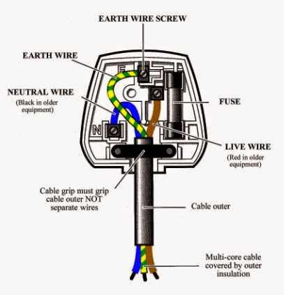
1. Plug Top 13A wiring details

Figure 1: Method to wire Plug Top 13A

2. Wiring diagram for Single Phase Energy Meter and MCB 32A

Figure 2: Method to wire Single Phase Energy Meter and MCB 32A (mounted in Distribution Box 1)

3. Wiring diagram for Controller Board 1

Figure 3: Method to wire Current Sensor and LCD module on the IO Expansion Shield

Note:-
The IO Expansion Shield and RF Module (transmitter) no need to wired because both of this components is only need to placed/mounted on the socket that has been provided.

B) BETWEEN LINE 1 & LINE 2

1. Load 1 wiring details

Figure 4: One switch control one light (Load 1)
 
C) LINE 2

1. Wiring diagram for Single Phase Energy Meter and MCB 32A

Figure 5: Method to wire Single Phase Energy Meter and MCB 32A (mounted in Distribution Box 2)

2. Load 2 wiring details

Figure 6: One switch control two lights (Load 2)

3. Wiring diagram for Controller Board 2

Figure 7: Method to wire Current Sensor, LCD module and Bluetooth module on the IO Expansion shield

Note:-
The IO Expansion Shield, RF Module (receiver) and BTBee Explorer Regulated no need to wired because this components is only need to placed/mounted on the socket/shield that has been provided.
 
Project Outcome

The circuits that designed for each part of component will be combined according to the project requirements. Below is the complete circuit for Electricity Theft Detection Metering System that obtained from this activity:-

Figure 8: A circuit diagram for Electricity Theft Detection Metering System (complete circuit)

From the circuit diagram that has been designed above, it will be used as a reference for the hardware development work. Before that, each part of the circuit will be tested to ensure it works well. This tasks will be discussed on the next progress report from broad to narrow.

Tuesday 8 April 2014

WEEK 4

Date: 26/2/14

Introduction

As mentioned in the previous week, this week a existing flow chart will be redesigned exactly based on the project that are being made. The flow chart need to redesigned because the flow chart that made in the previous FYP session (FYP 1) is only a draft and not the exact flow chart that used in the project. However, the changes that made is not totally different with the existing flow chart. The function/flow of project is still similar as proposed in the FYP 1.

Objective 
  • To redesign flow chart exactly with the project that developed.
Problem Encountered

To create the flow chart, several factors need to be considered such as in term of their symbol. The symbols of flow chart is very important to make a readers understand the flow of project that made. Thus, the selection of flow chart symbol should be correct according to the function/flow of project that made. However, all this problem has been solved in the previous FYP session (FYP 1) by makes some research in website and other sources.

Project Description 

The flow chart that made is based on the existing flow chart in the previous post for FYP 1 on WEEK 5 and for the other thing is according to the project that are being implemented. The result that obtained is such the project outcome below.

Project Outcome

Below is the result that obtained from this activity:-

Figure 1: Actual Process Flow Chart (redesigned)
          
The Figure 1 above is the actual flow chart that has been redesigned according to the function/flow of project that made. Others information in term of their circuit diagram either for each part of hardware or combination for all parts of hardware (complete circuit) will be discussed in details on next progress report.   

Wednesday 2 April 2014

WEEK 3

Date: 17/2/14

Introduction

A block diagram become one of the important part in develop a project. This week the existing block diagram will be re-designed according exactly with the project that developed. The block diagram need to re-designed because some of the component that listed in FYP 1 was changed with the other component. The changes that made is for the purposes to reduce project costing and also to make the project become more efficient and easy to used.

Objective 
  • To re-design block diagram exactly with the project that developed.
Problem Encountered

From this activity, it does not give much problem because the block diagram that re-designed is still based on the previous block diagrams and only at the certain part/block is changed i.e. according to the two main criteria which are (1) the components that replaced and (2) based on the actual project.

Project Description 

The block diagram is re-designed by using a Microsoft Visio software. Each part of block diagrams is labelled and connected according to the project flow from the beginning until to the end of the project flow. The block diagrams that has been re-designed will be shown in the project outcome below.

Project Outcome

Figure 1: Block Diagram (re-designed)

The Figure 1 above is the block diagram that has been re-designed according to the exact project flow that developed in FYP 2. The function/flow of Electricity Theft Detection Metering System is based on this block diagram. Others progress will be continued on next week.

Wednesday 19 March 2014

WEEK 2

Date: 11/2/14

Introduction

Project research is one of part that should to do in develop a project. It became an important thing to get a good project. In this FYP 2, the research that will be made will be separated by two parts i.e. for hardware part and software part. For the hardware part, the research that will be made is about the components that used in the project, the functions of each component, wiring diagram and the test procedures that should be made for each component together with the expected results from the test procedure while for the software part, the research that will be made is specific on the program codes in term of how to program, how to test each part of program code and the method to burn the program codes in the integrated circuit (IC). This project research will be made until the expected result for this project meets.

Objective 
  • To investigate and learn parts of hardware and software related with the project.
  • To list and show both of part (hardware and software) that used in the project.
  • To explain all the information that obtained from the research.
  • To ensure the project prototype meets.
Problem Encountered

Both of parts (hardware and software) have a problem. For the hardware part, the problem is about to find the energy meter and current sensor. It is because to get both of this component, it need to ordered and will take about 1 week above for a shipment process. For the software part, the problem is in term of to programs according to the expected results in this project and it is become a major problem in this project. Thus, several initiative will be taken for the purposes to solve this problems i.e. find other shop that may give shortest time for the shipment process and do more research on the programming part.

Project Description 

First of all, each components that needed in this project is examined in terms of their specifications for the purposes to validate the project prototype meets before making any purchasing. After that, the components that has been examined and verified suitable to used is recorded in a shortlist together with the image and specification of the component. Below is the results that has obtained from this activity:-

Hardware parts

Figure 1: List of Hardware

The specifications for each part of hardware
  1. Arduino Mega 2560
  2. Current Sensor 
  3. Single Phase Energy Meter 
  4. BTBee Explorer Regulated 
  5. IO Expansion Shield
  6. Plug Top 
  7. Light Bulb 
  8. RF Module
  9. 1 - Way Switch 
  10. Bluetooth Module 
  11. MCB 32A 1Pole 6kA 
  12. 16X2 Character LCD Module 
  13. Bulb Holder 
  14. 4 - Ways Plastic Distribution Box 
  15. PVC Junction Box 
Software parts

Figure 2: List of Software

The Arduino IDE environment
  1. Language Reference
  2. Examples
Other parts

Figure 3: List of other parts

The specifications for other parts
  1. USB 2.0 AM/BM
  2. 1 Pin Dupont Connector Housing
  3. 3 Pin Dupont Connector Housing
  4. Male Crimp Pin
  5. Female Crimp Pin
  6. Wire
  7. Soldering Tool Kit
  8. Hand Tools
  9. Plywood - 36"H x 18"W x 0.35"D
  10. Aerosol Paint - Black
  11. 7mm Cable Clips
Project Outcome 

All the components that needed in this project has been investigated and recorded. The results that obtained from this activity will be used for the purpose of purchasing and booking. On the other hand, some of the component also has been changed with the other component and the changes that has been made is such as below:-
  1. Arduino Uno Rev3 ---- Arduino Mega 2560
  2. GSM Module ---- Bluetooth Module 
  3. Current Transformer ---- Octopus Non-invasive AC current sensor (TA12-100) Brick 
This components is changed because (1) Arduino Mega 2560 have more I/O port compared with the Arduino Uno Rev3 (compare board specs), (2) in term of price, Bluetooth module is cheaper than GSM module and, (3) in term of current measurement, Octopus Non-invasive AC current sensor (TA12-100) Brick is more compatible and accurate compared with the current transformer. Thus, this is the best solution to ensure project prototype meets. The others information in term of wiring diagram, test procedures (hardware and software) and all thing about the program codes will be discussed after the tasks for redesign a block diagram and flowchart is completed made on the next week.  
                   

Friday 14 March 2014

WEEK 1

Date: 5/2/14

Title of activity
  1. Short discussion with project supervisor.
  2. Project scheduling.
Objective
  • To update any related matter that has been made for FYP 2 to the project supervisor.
  • To manage weekly activities that will be made systematically.
  • To ensure all task that should be made completed on time.
Content/Procedure

The main objective of this discussion is to update any progress that has been made for FYP 2 to the project supervisor. Simply, the content in this discussion is about the FYP 2 assessment that should be made in term of the due date for submission, report formats, report contents and etc. On the other hand, in order to fulfill subject requirement according to the date line that given, a gantt chart will be created to make it as a guidelines and to ensure all task completed on time.

Result/Outcomes

The outcome from this activity is such as the Figure 1 below:-

Figure 1: Gantt Chart for FYP 2

Conclusion

All the information that should be taken for the FYP 2 assessment has been recorded and highlighted. All tasks that related with the FYP 2 will be referred on that gantt chart until at the end of the date line for FYP 2. For the next progress report, the topic that will discussed is specific about the project research that made for FYP 2.