Introduction
In develops a project, aside from design a gantt chart, block diagram and flow chart, the other thing that need to made is design a circuit diagram. The circuit diagram will become as a reference to wire the overall project according to the project that needed. Thus, to design the circuit diagram, a suitable software need to used to makes the circuit diagram that designed clear, standard and able to understood by others. Generally, in the real applications, the circuit drawing or technical drawing is designed by using AutoCAD software, but since a skill to use that software are quite weak, one of the initiative/solution for that problem is by using a Microsoft Office Visio. From this solution, the circuit diagram that designed will look clear and easy for anyone to understand the drawing.
Objective
- To design the circuit diagram based on the actual project applications.
- To shows the circuit diagram for each part of hardware and for the overall part of hardware (complete circuit).
From this activity, the problem that encountered is in terms of to read and understand each datasheet. It is because all the information that given in the datasheet need to understood which is for the purposes (1) to avoid from any damage on the component, (2) to connect/wire exactly on each terminal board/port that should be connected only. On the other hand, the methods about how to use the Microsoft Office Visio software does not become a problem because this software is always used in designing the block diagram, flow chart and etc.
Project Description
First of all, once all the data about each part of hardware that need to known is identified correctly, part by part of the hardware will be wired separately. Below is the methods to wire each part of the component used in the Electricity Theft Detection Metering System:-
A) LINE 1
1. Plug Top 13A wiring details
 |
| Figure 1: Method to wire Plug Top 13A |
2. Wiring diagram for Single Phase Energy Meter and MCB 32A
 |
| Figure 2: Method to wire Single Phase Energy Meter and MCB 32A (mounted in Distribution Box 1) |
3. Wiring diagram for Controller Board 1
 |
| Figure 3: Method to wire Current Sensor and LCD module on the IO Expansion Shield |
Note:-
The IO Expansion Shield and RF Module (transmitter) no need to wired because both of this components is only need to placed/mounted on the socket that has been provided.
B) BETWEEN LINE 1 & LINE 2
1. Load 1 wiring details
 |
| Figure 4: One switch control one light (Load 1) |
C) LINE 2
1. Wiring diagram for Single Phase Energy Meter and MCB 32A
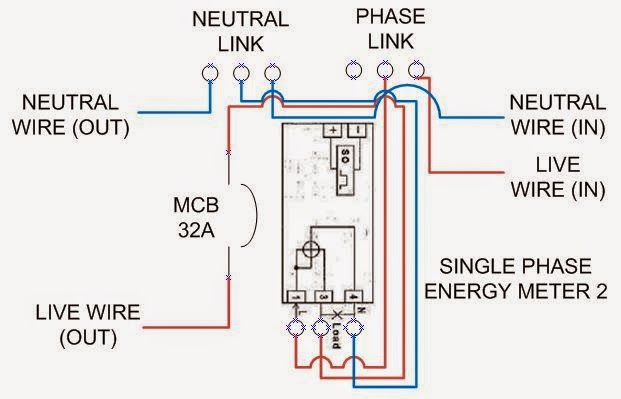 |
| Figure 5: Method to wire Single Phase Energy Meter and MCB 32A (mounted in Distribution Box 2) |
2. Load 2 wiring details
 |
| Figure 6: One switch control two lights (Load 2) |
3. Wiring diagram for Controller Board 2
 |
| Figure 7: Method to wire Current Sensor, LCD module and Bluetooth module on the IO Expansion shield |
Note:-
The IO Expansion Shield, RF Module (receiver) and BTBee Explorer Regulated no need to wired because this components is only need to placed/mounted on the socket/shield that has been provided.
Project Outcome
The circuits that designed for each part of component will be combined according to the project requirements. Below is the complete circuit for Electricity Theft Detection Metering System that obtained from this activity:-
 |
| Figure 8: A circuit diagram for Electricity Theft Detection Metering System (complete circuit) |
From the circuit diagram that has been designed above, it will be used as a reference for the hardware development work. Before that, each part of the circuit will be tested to ensure it works well. This tasks will be discussed on the next progress report from broad to narrow.
No comments:
Post a Comment