Saturday, 31 May 2014

WEEK 13 & WEEK 14

Date: 7/5/14

Introduction

This week is the last week before project presentation day will be held. All the requirements that needed for that week should be prepared properly. Student shall present their complete project outcome as scheduled by Campus which is at the end of week 14. Failure to attend the presentation will cause student to receive the failure grade (F). The project presentation will be held at Gemilang Hall and start from 8.00 am till 12.30 pm. Students will be assessed by two persons of invited assessor from related department with the project title.

Objective
  • To finalize a preparation that should will be made for presentation day
  • To ensure all the assessment criteria is achieved perfectly
  • To makes some preparation for Q&A session
Problem Encountered

All the requirement that needed such as project poster, project prototype and others has been made and meets all the required assessment criteria which means the first and second of the objective is achieved perfectly. However, a bit of problem occurs in makes some preparation for Q&A session. It is in terms of student did not know what questions that would be asked by supervisors in that session. As a solution, the proposal presentation assessment that prepared by FYP committee will be made as a guideline in preparation for Q&A session.

Project Description

The entire criteria that needed in the project presentation day will be fulfilled by referring the proposal presentation assessment that given by FYP committee. Below is a copy of the documents that given:-

Figure 1: Project Presentation Assessment

Figure 2: Project Presentation Assessment (Cont.)

Figure 3: Project Presentation Assessment (Cont.)

All the preparation for the project presentation day will be referred from this documents.

Project Outcome

Referring from the official website of UniKLBMI-FYP, under list of deg sem 2 assessors, it shows that for this project it will be assessed by (1) Sir. Mohamed Razif Mohd Noordin and (2) Mdm. Zurin Zuraida Bte Abu Baharin. As a conclusions, everything has been prepared and achieve all required assessment criteria. Hopefully, everything is smoothly during that presentation day.

WEEK 12

Date: 28/4/14

Introduction

Project presentation is one of the assessment in FYP 2 that will be made at the end of semester 7. The assessment is based on individually basis. It will be assessed by Project Supervisor and Invited Assessor. The overall mark obtained by students is the average mark given by Supervisor and second Assessor. This week, a preparation for project presentation day will be made and discussed clearly.

Objective
  • To make some preparations before project presentation day
  • To making a project poster according to the assessment criteria that given
Problem Encountered

From the activity on this week, its does not have much problem because the contents that should be put into a poster is from the assignments that has been made along this semester. The things that need to be made only extract all gathered information briefly, concise and easy to understand.

Project Description

All gathered information will be extracted in a simple way to understand according to the assessment criteria that needed. The poster also will be decorated to look more attractive because sometimes people will bored when too much of word inserted in the poster. As a solution, several information will be described by using a SmartArt graphic to visually communicate information. A background picture also will be used and inserted in the poster.

Project Outcome

Below is the poster that have been made for project presentation day.

Figure 1: Project Poster

The completed poster will be shown to the project supervisors before project presentation day. As a conclusions, all tasks for this week completed perfectly and the poster that has been made has been approved by project supervisor. For the next progress report, the things that made before/during/after presentation day will be briefly discussed.

Friday, 30 May 2014

WEEK 11

Date: 22/4/14

Introduction

Project costing is the amount of the overall cost to build a project that usually contains the amount of cost for each parts of hardware, software and miscellaneous part used in the project. This week, the costing for that part will be discussed and shown in details.

Objective 
  • To list and show cost for each part of hardware, software and miscellaneous part used in the project.
  • To shows the total cost of project.
Problem Encountered

In this activity, the problem that encountered is in terms of to find a good components at low prices. It is because usually the good components will be sold at high prices. Several initiative will be taken to solve this problem such as make a observation at a few store that sell required components at low prices before buying that component.

Project Description

When the store that sell required components at needed prices have been found, buying process will be made till all the required components is obtained. Then, each part of components that have been purchased together with the prices is recorded in three part such mentioned in the objective above. The results from this activities are as shown in the Project Outcome below.

Project Outcome 

There are three parts in this project outcome which are hardware costing, software costing and miscellaneous costing. Below is the figure that shows each parts of this costing together with the total cost of project.

Hardware Costing

Figure 1: Hardware Costing
   
Software Costing

Figure 2: Software Costing

Miscellaneous Costing

Figure 3: Miscellaneous Costing

Total Cost

Figure 4: Total Costing

Total cost of this project is about RM 1229.35. It is quite expensive. However, this is the best choice from various electronics store that have. In the next progress report, all works related with the project presentation will be discussed and shown clearly.

Tuesday, 20 May 2014

WEEK 10

Date: 14/4/14

Introduction

In this parts of progress report, the things that will be discussed is about the functional tests for the overall project. It covers the functional tests for both part which are pole and consumer based system together with the bluetooth module. All the transmitted data from pole based system and the received data at the consumer based system also will be shown through the LCD display. Further, the bluetooth module that used in this project also will paired and connected to the handphone or other devices that can paired with the bluetooth module used to demonstrates the actual result needed in the entire project.

Objective
  • To makes a functional tests to the overall part of project.
  • To ensure all required criteria and the expected results in this project meets.
Problem Encountered

This project do not have any problem because the test procedure that made is only to obtain the expected results from the overall project. Simply, it only need to 'plug and play' and record all the results that obtained.

Project Description

Step 1

First of all, power up main circuit by connects the plug top to the socket outlets. Once connected, switch on both MCB and both digital energy meter will display current power usage and measured in kWh. Below is the result from this part.

Figure 1: Power usage from both part of measurement

Step 2

Switch on both Arduino board and the LCD will display the characters that have been programmed. Once completed displays all the characters, each LCD at pole and consumer based system will display current reading depend on the loads that used. The results for this part is as that have been shown on previous week (week 8 and week 9) under project outcome.

Step 3

Download Bluetooth Terminal software from Google Play website and install this software to the handphone to display all the data that transmitted from the bluetooth module. The results for this part as shown in the Project Outcome below and demonstrated in two different condition which are without unauthorized loads and with unauthorized loads.

Project Outcome 

The results obtained from the overall part of this activities are as follows:-

Without unauthorized loads

Figure 2: Result for without unauthorized loads
    
With unauthorized loads

Figure 3: Result for with unauthorized loads

Based on the results obtained from the overall part of this activities, it shows the expected results is achieved according to the project requirement. Thus, for the next progress report, all things that related with the project costing will be shown and discussed in details.

Monday, 19 May 2014

WEEK 9

Date: 7/4/14

Introduction

This progress report will discuss about the software development that made for consumer based system. The things that will be discussed is in terms of the source code for consumer based system together with the project outcome from this activity. However, it still relate with the works that made in the previous week (week 8) because a few parts of source code and data are from the pole based systems.

Objective
  • To writing and maintaining the source code.
  • To modify and reuse the source code with respect to the desired outcome of the project.
  • To test and integrate the source code with the components used in the project.
Problem Encountered

The problem encountered from this activity is in terms of to find the source code for receive the transmitted data from pole based system. It is because the source code that used for the receiving part is different with the transmitting part. It is because the source code that used for the receiving part is different with the transmitting part. On the other hand, the compatibility of the source code with the RF module also need to be considered because it will be affect to the speed of data that transmitted to the receiver. Thus, as a solution, various websites about the source code for RF module together with the method of 'trial and error' will be used to solve this problems until success.

Project Description 

Below is the steps used in this part of software development:-

Step 1

Open a Arduino IDE and check the libraries that have in the IDE that used for confirmation. In this part the libraries that used is similar with the previous part. Thus, no additional libraries will be installed. 

Step 2
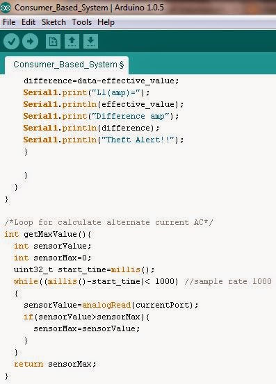
Sketch the source code according to the required codes in the Arduino IDE and the source code that have been made is such as below.

Figure 1: Source code for consumer based system
     
Figure 2: Source code for consumer based system (Cont.)

Figure 3: Source code for consumer based system (Cont.)

Step 3

Once all required source code is completed sketched in the text editor, all the completed source code need to verified before uploaded in the Arduino board. Below is the result obtained from the verification of source code that made in the Arduino IDE.

Figure 4: Source code verification results

Step 4

When the source code is verified not have an errors, set the Arduino board model and COM that currently used in the Arduino IDE. In this project, the Arduino board model and current USB port (COM) that used is Arduino Mega 2560 and connected to the COM 11. Once selected, both of this information will appears at the bottom of Arduino IDE such as shown in the Figure 5 below.

Figure 5: Current Arduino board model and USB port

Step 5

Upload all the source code in the Arduino by using the button for compile and upload sketch to Arduino at the top of Arduino IDE. Once completed uploaded, it can be seen directly on the hardware part (LCD) and the results as in the Project Outcome below.

Project Outcome

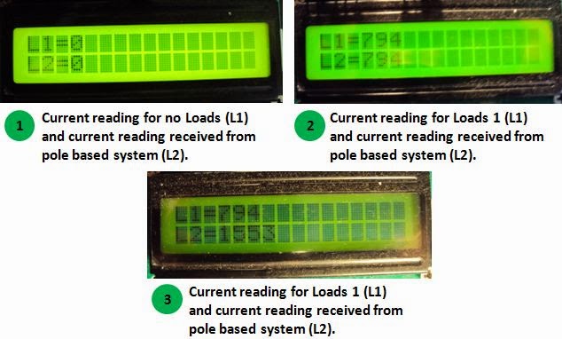
Below is the results obtained from the source code that made for consumer based system and demonstrated in three different condition together with the current reading that received from pole based system.

Figure 6: LCD displays current reading for three different conditions together
with the current reading that received from pole based system

Based on the Figure 6 above, it shows all the required results have been achieved according to the criteria that needed for the consumer based system. Thus, the functional tests for the overall project together with the Bluetooth module will be made and discussed in the next progress report.

WEEK 8

Date: 31/3/14

Introduction

Software development is the development of a software product. The term "software development" is used to refer to the activity of computer programming, which is the process of writing and maintaining the source code. This week, the development of software will be made, discussed and shown according to the specific requirement needed in the entire project.

Objective
  • To writing and maintaining the source code.
  • To modify and reuse the source code with respect to the desired outcome of the project.
  • To test and integrate the source code with the components used in the project.
Problem Encountered

Software development is usually implemented by using a specific software and based on the microcontroller board or integrated circuit (IC) that used. As mentioned before, this project (ETDMS) is controlled by using Arduino Mega 2560 and this microcontroller board have their own software application known as Arduino IDE. This software application provides comprehensive facilities to computer programmers for software development. However, it have a few things that need to known and learned in terms of the language and libraries because both of this part is very important in the software development. Even it have been provided in the Arduino website, it will become a problem if the language and libraries that used is not compatible and suitable with the components. Thus, as a solution, each required libraries will be ensured compatible, suitable and installed with the IDE together with the correct language/source code.

Project Description

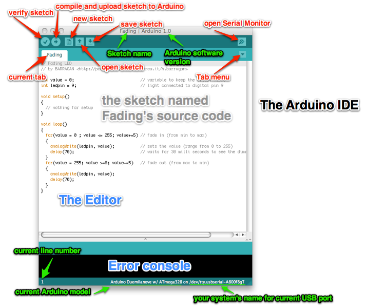
The Arduino IDE contains a text editor for writing code, a message area, a text console, a toolbar with buttons for common functions, and a series of menus. It connects to the Arduino hardware to upload programs and communicate with them. The following is the procedures for the overall parts of this activities.

Step 1

First of all, the Arduino IDE need to identified and the Figure 1 below shows the Arduino IDE together with the explanation for each parts of the Arduino IDE.

Figure 1: The Arduino IDE
        
Step 2

Once all term in the IDE window is identified, check the libraries as shown in the Figure 2 below.

Figure 2: List of libraries installed in the Arduino IDE.

Step 3

When all the required libraries have been installed in the Arduino IDE, sketch the source code in the text editor according to the project requirement. Since this project (ETDMS) uses two microcontroller board, the source code also should be made in two parts named as (1) pole based systems and (2) consumer based systems.

Figure 3: Source code for pole based system

Figure 4: Source code for pole based system (Cont.)

Step 4

Once all required source code is completed sketched in the text editor, all the completed source code need to verified before uploaded in the microcontroller board. Below is the result obtained from the verification of source code that made in the Arduino IDE.

Figure 5: Source code verification results
 
Step 5

When the source code is verified not have an errors, set the Arduino board model and COM that currently used in the Arduino IDE. In this project, the Arduino board model and current USB port (COM) that used is Arduino Mega 2560 and connected to the COM 11. Once selected, both of this information will appears at the bottom of Arduino IDE such as shown in the Figure 6 below.

Figure 6: Current Arduino board model and USB port
   
Step 6

Upload all the source code in the Arduino by using the button for compile and upload sketch to Arduino at the top of Arduino IDE. Once completed uploaded, it can be seen directly on the hardware part (LCD) and the results as in the Project Outcome below.

Project Outcome

Below is the results obtained from the source code that made for pole based system:-

Figure 7: LCD displays current reading for three different conditions
     
The Figure 7 above shows the results that obtained from the source code that made for pole based system. All needed data that should be displayed on the LCD for pole based system have been achieved according to the required criteria. Further, this data need to transmitted to the consumer based system using RF module and suitable source code to allows the data obtained from pole based system can be transmitted and received at the consumer based system repeatedly and according to the loads that used over time. Thus, the other source code for that purpose will be sketched and shown in the next progress report.